The Dillon Primer Early Warning System is a simple but robust product. However if you leave a battery in there it will corrode all of the internal electronics. This was the case with two units I was given to fix. Internally one of the batteries was in two pieces, the acid and acidic fumes had eaten away the copper wire, destroyed the buzzer and was all over the micro switch and most likely also inside it.
On stripping out the electrical parts I found the bottom battery spring showed no signs of corrosion at all. The plastic case was covered in muck but was easily cleaned after a good soaking in sodium bicarbonate to neutralize the acid.
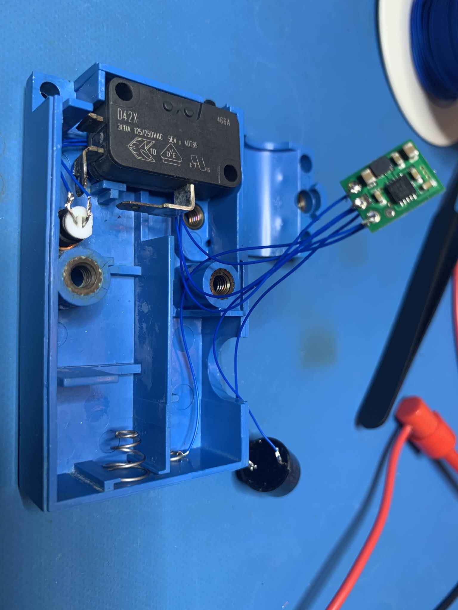
The electric are very simple. a micro switch where the common contact is used for the battery contact. There are two contacts on the side the top one is cut, which the normally closed contact. The bottom contact is normally open which is connected to a wire to the buzzer. From the buzzer runs a second wire to the spring which is the contact for the other end of the battery.
When talking about the repair I also discussed what else could be done to upgrade the product. Basically we came up with 3 things.- A louder buzzer : as older long term shooters tend to be a bit deaf
- A bright red warning light : again due to deafness
- A way to still run it off of a 1.5 Volt AAA battery
This particular unit had an electro-mechanical buzzer that was totally corroded. I stripped out the insides but retained the plastic case to hold the Piezo buzzer.
It should be noted that most Piezo speakers will NOT make any noise with out and external oscillator. When purchasing one ensure it has a BUILT IN OSCILLATOR.
It also turns out that the Piezo buzzer in the new Dillon products is already
at the 85dB limit. Going louder than that will just worsen you hearing
further.

 The second picture shows the stripped down components with the LED in place.
To add a LED light it was easier to source 3.3 volt parts. However as the device can only take a single AAA battery at 1.5 volts I needed a boost converter.

1 x 3.3 Volt boost converter - Pololu 3.3V Step-Up Voltage Regulator U1V10F3 - $7 AUD
1 x 3 Volt high brightness LED - TLDR4900 LED, 3MM, RED - $2.96AUD for 5
1 x 3mm LED holder - A104700BLACK LED HOLDER, T1, PK5 - $15.61 for 5
1 x 3.3 Volt PiezoIndicator - Continuous tone magnetic 3Vdc 85dB HS code 85318000 - $13.85 for 5
1 x 150 Ohm resistor - This is for the LED, to stop it drawing too much current.
1 x Double sided tape -
1 x Spool wire wrap wire -


