Monday 19 October 2020

Dillon Primer Early Warning System - Rebuild and Modification

The Dillon Primer Early Warning System is a simple but robust product.  However if you leave a battery in there it will corrode all of the internal electronics.  This was the case with two units I was given to fix.  Internally one of the batteries was in two pieces, the acid and acidic fumes had eaten away the copper wire, destroyed the buzzer and was all over the micro switch and most likely also inside it.

On stripping out the electrical parts I found the bottom battery spring showed no signs of corrosion at all.  The plastic case was covered in muck but was easily cleaned after a good soaking in sodium bicarbonate to neutralize the acid.

The electric are very simple.  a micro switch where the common contact is used for the battery contact.  There are two contacts on the side the top one is cut, which the normally closed contact.  The bottom contact is normally open which is connected to a wire to the buzzer.  From the buzzer runs a second wire to the spring which is the contact for the other end of the battery.

When talking about the repair I also discussed what else could be done to upgrade the product. Basically we came up with 3 things.
  1. A louder buzzer : as older long term shooters tend to be a bit deaf
  2. A bright red warning light : again due to deafness
  3. A way to still run it off of a 1.5 Volt AAA battery

This particular unit had an electro-mechanical buzzer that was totally corroded.  I stripped out the insides but retained the plastic case to hold the Piezo buzzer.

It should be noted that most Piezo speakers will NOT make any noise with out and external oscillator.  When purchasing one ensure it has a BUILT IN OSCILLATOR.

It also turns out that the Piezo buzzer in the new Dillon products is already at the 85dB limit.  Going louder than that will just worsen you hearing further.

I bought some LED holders to hold the LED light as you can see from this picture when mounted it looks pretty swish.  


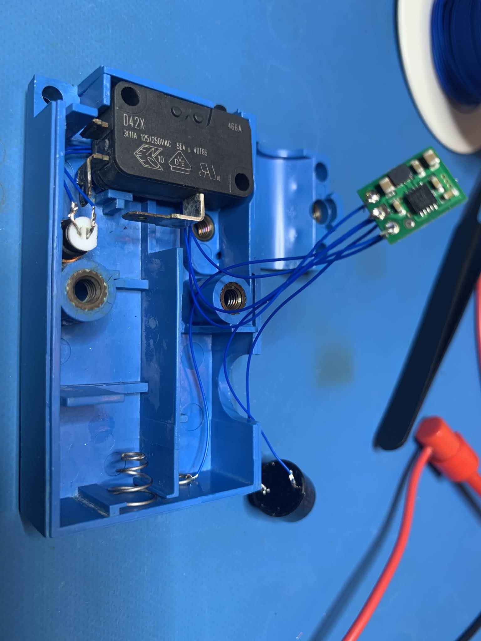
The second picture shows the stripped down components with the LED in place.

To add a LED light it was easier to source 3.3 volt parts.  However as the device can only take a single AAA battery at 1.5 volts I needed a boost converter.

 
BOM
 

1 x 3.3 Volt boost converter          -       Pololu 3.3V Step-Up Voltage Regulator U1V10F3 - $7 AUD

1 x 3 Volt high brightness LED    -      TLDR4900 LED, 3MM, RED - $2.96AUD for 5

1 x 3mm LED holder                    -    A104700BLACK LED HOLDER, T1, PK5 - $15.61 for 5

1 x 3.3 Volt PiezoIndicator           -    Continuous tone magnetic 3Vdc 85dB HS code 85318000 - $13.85 for 5

1 x 150 Ohm resistor                        This is for the LED, to stop it drawing too much current.

1 x Double sided tape                    - 

1 x Spool wire wrap wire               -

 
As you can see space was pretty tight but the end result had a nice professional finish. 


Wednesday 14 October 2020

Sony WH-1000XM3 - Replacing the USB-C connector

I've been fairly consistantly doing a lot of soldering over the last few years, both surface mount and through hole.  Every now and then I accept "easy" jobs from my friends.  I've fixed buttons on car key fobs, micro usb connectors and now the USB-C connector on Sony WH-1000XM3 head phones.

This has probably been the first item where I've not been able to get to the pins to solder them on.  So lets have a look at what is involved.

Deconstruction

The headphones are really nicely put together and very repairable, something other manufacturers should take note of.


Using a spudger start at the side and make your way around to remove the foam ear piece.


Luckily there are only screws and a bit of tape holding it together.  Remove the first flexible connector.


Remove the plastic cover to expose the USB-C connector


Remove the second flexible connector and the small PCB. Look at that mess of crushed pins.


Using a Hot Air tool remove the connector.  You'll notice I've left the solder on the pads.


Which part is this?


Now that I had the part off it was off to RS-Components to play match the foot print.  With some digital calipers in hand and data sheets on the screen I managed to find a good match.


Reconstruction


I left the solder on the pads on purpose so I could reflow it with my Quick 861DW.
Carefully tin the small connector pins.
Place back on the PCB.
Now use your Hot air tool to relflow it with a little downward pressure. Keep the air down quite low. I had it on 40 l/min
 

Make sure you secure it properly as you do not want it to break off.

 
It lives . . . actually I tested it quite a bit before putting it back together.

Thursday 7 May 2020

Abandon ship . . .

Well not really . . . 

I've started focussing on just my retro projects so if you're interested in on old Commodore related stuff that I'm working on head off to https://8bitshardway.blogspot.com/

Hopefully I can jam some interesting CPLD FPGA stuff in there :-)


Monday 24 April 2017

FPGA's

For some reason I find these things fascinating, so I've started some more projects that I'll probably never ever finish.

There are a lot of really good projects out there for learning FPGA's and some really good stuff rebuilding retro computers.

Two I've taken an interest to are the MIST and the MEGA65.  Mainly because I am a child of the 70/80's and grew up in an age when you could really understand how your computer really worked.

Now I haven't got a clue about HDL ( VHDL or Verilog ) so I'm really just stuffing about but if you can get yourself the required hardware to run the cores here are my notes on how to build them on the latest ( at the time of writing ) Ubuntu distribution. Which surprisingly wasn't that hard to do.

This was all done in Vmware workstation 12.

Installing Xilinx 14.7 and Compiling the MEGA65 Core

1) Get Ubuntu Desktop 17.04
    https://www.ubuntu.com/download/desktop
    Do a default install.

2) Install everything in ~/Documents
    cd ~/Documents
    mkdir MEGA65
    cd MEGA65

3) Install git, libpng-dev
    sudo apt-get install git
    sudo apt-get install libpng-dev

3) Get git repositories required
    git clone https://github.com/MEGA65/mega65-core.git
    git clone https://github.com/gardners/Ophis.git
    git clone https://github.com/sasq64/cbmconvert.git

4) Compile and install cmbconvert
    cd ~/Documents/MEGA65/cbmconvert
    make -f Makefile.unix
    sudo make install

5) Download Xilinx 14.7 WebPACK
    https://www.xilinx.com/support/download/index.html/content/xilinx/en/downloadNav/design-tools.html
    As I wish to use both Windows and Linux I got this file :
         Full DVD Single File Download Image (TAR/GZIP - 7.78 GB)
   
6) Create an account and get a FREE Webpack License
    https://www.xilinx.com/registration/sign-in.html?oamProtectedResource=wh%3Dwww.xilinx.com%20wu%3D%2Fmember%2Fforms%2Flicense-form.html%20wo%3D1%20rh%3Dhttp%3A%2F%2Fwww.xilinx.com%20ru%3D%252Fmember%252Fforms%252Flicense-form.html
    OR
    Wait until after the install

7) Install Xilinx 14.7
    cp Xilinx_ISE_DS_14.7_1015_1.tar ~/Documents/
    cd ~/Documents
    tar xvf Xilinx_ISE_DS_14.7_1015_1.tar
    cd ~/Documents/Xilinx_ISE_DS_14.7_1015_1
    sudo ./xsetup
    Accept multiple license agreements
    Choose ISE WebPACK from Edition List
    Don't install cable drivers . . .
    Install to default /opt/Xilinx

    You can remove Xilinx_ISE_DS_14.7_1015_1.tar and Xilinx_ISE_DS_14.7_1015_1.tar as they are no longer needed.

8) Start ISE for the first time and add your license ( or get one )
    . /opt/Xilinx/14.7/ISE_DS/settings64.sh
    ise

9) Add settings to your .bashrc so it is available every time you log in and/or start a terminal
    cd ~
    vi .bashrc
    Add this line to the end of the file
    . /opt/Xilinx/14.7/ISE_DS/settings64.sh

10) Compile the mega65 core
    cd ~/Documents/MEGA65/mega65-core
    ./compile.sh

11) Wait . . . this took about 53 minutes in the VM.  However the resulting core worked perfectly

Installing VMware Tools


1) Add source code to the list of Source repositories
    Click on the Ubuntu Icon and type Software, then click on "Software & Updates"
    Under the TAB Ubuntu Software, check the "Source Code" checkbox
    While you are there also pick a repository close to you, preferrably one you can get free downloads from
    in the "Download from:" Dropbox.

2) Install the source code
    apt-get source linux-image-$(uname -r)
   

3) Unzip and untar the tools and run the installer picking ALL of the default options
    cp VMwareTools-10.1.6-5214329.tar.gz /tmp
    cd /tmp
    gzip -d VMwareTools-10.1.6-5214329.tar.gz
    tar xvf VMwareTools-10.1.6-5214329.tar
    cd vmware-tools-distrib/
    ./vmware-install.pl

ALTERA Quartus II 13.1 - for the MIST


0) Get Altera Quartus II 13.1
    http://dl.altera.com/13.0sp1/?edition=web

    I got the Linux version, it's 4.5GB in size.

1) You will need to install the 32 bit version of the system libraries
    sudo bash
    dpkg --add-architecture i386
    apt-get update

    apt install apt-file            # We need to find 32 bit packages
    apt-file update                #  so use apt-file to search
    apt-file seach <package>        #  for them

    apt-get install libc6:i386         # Not too sure about the first 3
    apt-get install libstdc++6:i386     #
    apt-get install expat:i386        #
    apt-get install libfreetype6:i386    # But you definitely need these ones
    apt-get install libsm6:i386        #
    apt-get install libxrender1:i386    #
    apt-get install libfontconfig1:i386    #
    apt-get install libxext6:i386        #

2) Get a really old version of libpng12 both 32 and 64 bit.
   Because you can't symlink the new version and have it work as the Qt library it uses looks
   at the version number in the library.

    http://packages.ubuntu.com/xenial/amd64/libpng12-0/download
    http://packages.ubuntu.com/xenial/i386/libpng12-0/download

    dpkg -x libpng12-0_1.2.54-1ubuntu1_i386.deb outfiles
    cd outfiles/lib
    cp * /usr/lib/i386-linux-gnu/

    dpkg -x libpng12-0_1.2.54-1ubuntu1_amd64.deb outfiles54
    cd outfiles/lib/x86_64-linux-gni
    cp * /usr/lib/x86_64-linux-gnu/
   
3) Make a directory and untar the installer
    mkdir Altera
    cd Altera
    tar xvf Quartus-web-13.1.0.162-linux.tar .

4) Edit the setup file and change the first line From
    #!/bin/env bash
   To
    #!/bin/bash

5) Open a new terminal
    xhost +                  # Not sure about this as the graphical installer didn't work anyhow
    sudo bash
    ./setup.sh

6) It will go to the command line installer
    Press Enter lots
    Then hold down Enter for the agreement
    Then choose Y
    Then choose a new directory : /op/altera/13.1
    Then choose the defaults ( basically install the Free stuff )
    Wait . . .
    Do defaults

7) Start Quartus II
   Now both versions run:
    cd /opt/altera/13.1/quartus/bin
    ./quartus        # for 32 bit
    ./quartus --64bit    # for 64 bit

Compile the MIST C64 Core

1) Download and Compile C64 core for mist
    cd ~/Documents
    mkdir C64
    cd C64
    git clone https://github.com/sorgelig/C64_MIST.git

2) Start Quartus II
    Open Project and Compile

    It takes about 3mins 41 secs

    ~/Documents/C64/C64_MIST/output_files/C64_mist.rbf


Saturday 18 March 2017

Cutting code . . .

Cutting code

Probably the part I like least about this project, cutting code.  I started off my career in IT writing bits of C for spatial data manipulation and server software on Unix, but never got into UI and Windows programming, in fact I pretty much hate it.  Which is why I'm a database admin/programmer now I guess any I digress.

Finding example code to do what I wanted was surprisingly hard.  I did find this little gem but it was in Visual Basic from Hackshed.  However it did have Bluetooth code that works straight out of the box ( well after getting the baud rate right ).

With a few little tweaks I managed to get it up and running but as I have no clue how to write VB I got a little stuck on threading and adding bits and pieces to the interface.  Luckily I have proper Windows programmer friends who could had it for me.

So the interface from Hackshed was modified to do the following.

* Drive both motors from -255 to +255. 0 being off.
* Read the RFID reader output.

So currently I'm waiting for my friend to send me back a new version that he converted to C# and added some better handling between the Arduino and the PC.

So what is my aim here.  Well I want the Arduino to just be a relay, I don't want it to have any smarts at all.  The C# interface will basically set and keep track of speed and also the RFID tags it passes over.

Hopeful Operational Theory

 RFID tags being uniquely numbered means that I can use them for location and also function.

The interface will store each tag in a database.  New tags will request the user for details.

Each tag will be used to add location and build a track map using linked lists.

Function Tags will initially be for the following.

1) Reverse for end of track
2) Stop signals ( start and stop ).
3) Speed signs ( for slowing and speeding around turns etc ).
4) Time stop delay ( for stations stops ).

I don't have anything for track switches.  There is commercial product for this so I might use that as it looks nice,

New nodes should be added as they are encountered and placed in the correct location in the list.

Location Tags will identify trains on a portion of track.   This should enable the following.

1) Location
2) Direction ( after passing two tags )
3) Collusion detection and management ( either by right of way or using Stop Signals ) for multiple trains.

Don't hold your breath

Well it's taken me about two years to actually get it to this point, because there is just waayyy too much other cool stuff to do and I want to do it all.

Besides the RFID is a bit flakey so we'll see how it works in practice once I get the new code from my mate ( and I put in all my peripherals instead of his ).

Fun with RFID

Fun with the ID-12LA

So looking at the sensor tech out there that people have implemented, I'm really not a big fan of all the wires that people are using to detect where the train is.  RFID probably isn't the best solution but I think it'll suit my needs a little better . . . if I can get it working.

So the module I got was the small ID-12LA from Sparkfun.  I Initially bought the starter kit with the USB serial reader and a few cards, but save yourself some cash and just get the reader.

You should also get the RFID Reader Breakout Board and also some standard pin headers ( 0.1" ) and some xbee pin ( 2mm ) headers as well.

Ok next step . . . ignore the pinout example on Sparkfun's website . . . it is incomplete, to the point of being frustratingly useless.

 I eventually found this on Instructables and even added my own two cents worth in a comment for clarity and emphasis on following Part 2 of the how to properly.

I was getting the FFFFFFF issue and other intermittent read issues.
The only thing that fixed it was to follow step 2 correctly with the wiring.
Ensure that you are using the +5V and NOT +3.3V
Tie pin 1(GND) and 7(FORMAT) together and connect to Ground
Tie pin 2(RES) and 11(+5V) together and connect to +5V
Pin 9 (D0) goes to RX on the Arduino
Pin 10 (LED) should go to an appropriate resistor, LED then Ground.

However a picture is worth a thousand words so here is my break out board with wiring.  The beauty of this wiring is that you only need to use one connector and three wires.


The wire I got was single core with insulation, so it was easy to solder and didn't cause a short.

I soldered all of the headers on first.

Once complete I soldered ( re-flowed ) the BLACK wire from GND to FORM.

There is a spare BLACK wire that goes from GND to nowhere, you don't need that one, it's just in case I wanted to solder a led and resistor to the READ pin for read notifications, but I don't want to now as it was only for debugging.  Also when the card/button is read there is a blue led on the MM v2 that will light up.

I then soldered ( re-flowed ) the RED wire from RES to VCC.

I crimped up the 6 Pin connector with three wires for VCC ( +3.3V ) , D0 ( Digital Sense Pin ) and FORM ( Ground ).